

Embedded Systems: Learning by Rule: CPU Theory and Firmware Development Rules
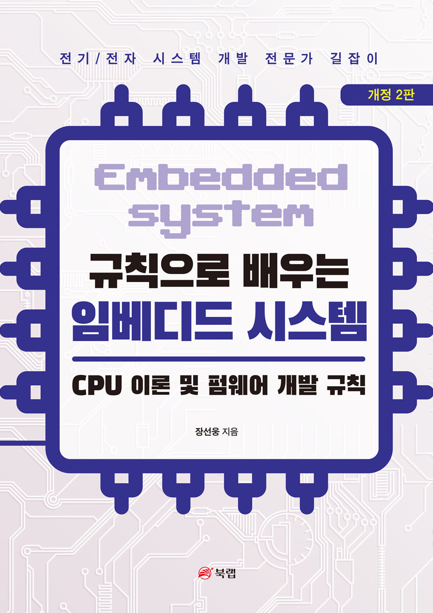 |
Description
Book Introduction
A Guide for Electrical/Electronic Systems Development Professionals
Electrical/Electronics from a Veteran Engineer
A clear roadmap for embedded system development!
"The best way to read this book is to read it repeatedly as if you were reading a novel to understand the basic theory and
"It's about understanding the relationships between system development rules."
CPU (Central Processing Unit) is defined as a central processing device that reads, interprets, and processes commands to perform the desired action.
Passive components, active components and semiconductor ICs.
A CPU is an IC that integrates circuits utilizing memory elements, particularly flip-flops, into a single package. It is considered the pinnacle of integrated circuits. The greatest advantage of CPUs, compared to systems designed solely with hardware, is that they allow for easier implementation and modification through software changes. Therefore, a thorough understanding of their structure and operation is essential, as they are used in most electrical and electronic systems.
While it would be valuable to delve into specific CPUs in detail, the goal here is to explore the general components and operations of a CPU, so that you can easily approach the subject even if the type of CPU you end up using changes.
Electrical/Electronics from a Veteran Engineer
A clear roadmap for embedded system development!
"The best way to read this book is to read it repeatedly as if you were reading a novel to understand the basic theory and
"It's about understanding the relationships between system development rules."
CPU (Central Processing Unit) is defined as a central processing device that reads, interprets, and processes commands to perform the desired action.
Passive components, active components and semiconductor ICs.
A CPU is an IC that integrates circuits utilizing memory elements, particularly flip-flops, into a single package. It is considered the pinnacle of integrated circuits. The greatest advantage of CPUs, compared to systems designed solely with hardware, is that they allow for easier implementation and modification through software changes. Therefore, a thorough understanding of their structure and operation is essential, as they are used in most electrical and electronic systems.
While it would be valuable to delve into specific CPUs in detail, the goal here is to explore the general components and operations of a CPU, so that you can easily approach the subject even if the type of CPU you end up using changes.
- You can preview some of the book's contents.
Preview
index
I. CPU Basics
1. CPU General
1.1. CPU structure and operation
1.2.
Command structure and executable files
1.3. Peripheral hardware for CPU operation
1.4.
Firmware boot process after reset
1.5.
interrupt
2. MCU (Micro Controller Unit)
2.1. GPIO
2.2. Considerations for Choosing an MCU
3.
Understanding how firmware works
3.1. CPU operation and binary file creation process
3.2.
Startup Programming Practice
II.
Firmware Development Rules
1.
Firmware design and implementation rules
1.1.
Firmware structure
1.2.
Firmware configuration
1.3.
Firmware security
1.4.
Firmware performance
1.5.
Mass production and maintenance of firmware
III.
Firmware design and development
1.
System Development Process
2.
System Requirements and Firmware Design
2.1.
System Requirements
2.2.
Firmware design
3.
Code implementation order as seen from the controller
3.1. ON/OFF controller
3.2.
Design and code implementation of a temperature controller
3.3.
Anti-chattering algorithm
4.
Data acquisition and processing
4.1. ADC and DAC&PWM
4.2.
Numerical analysis
4.3.
digital filter
5.
communication
5.1.
Serial communication in general
5.2.
Serial communication types
5.3.
Data Structures
5.4.
Modbus firmware implementation
IV.
[Reference] Debugging
1. CPU General
1.1. CPU structure and operation
1.2.
Command structure and executable files
1.3. Peripheral hardware for CPU operation
1.4.
Firmware boot process after reset
1.5.
interrupt
2. MCU (Micro Controller Unit)
2.1. GPIO
2.2. Considerations for Choosing an MCU
3.
Understanding how firmware works
3.1. CPU operation and binary file creation process
3.2.
Startup Programming Practice
II.
Firmware Development Rules
1.
Firmware design and implementation rules
1.1.
Firmware structure
1.2.
Firmware configuration
1.3.
Firmware security
1.4.
Firmware performance
1.5.
Mass production and maintenance of firmware
III.
Firmware design and development
1.
System Development Process
2.
System Requirements and Firmware Design
2.1.
System Requirements
2.2.
Firmware design
3.
Code implementation order as seen from the controller
3.1. ON/OFF controller
3.2.
Design and code implementation of a temperature controller
3.3.
Anti-chattering algorithm
4.
Data acquisition and processing
4.1. ADC and DAC&PWM
4.2.
Numerical analysis
4.3.
digital filter
5.
communication
5.1.
Serial communication in general
5.2.
Serial communication types
5.3.
Data Structures
5.4.
Modbus firmware implementation
IV.
[Reference] Debugging
Into the book
1.3.4. CPU Bus Structure
To understand the electrical process by which the CPU retrieves and writes data from memory, you need to understand the bus structure.
A bus is a bundle of signal lines with the same purpose, and is defined as a type of communication line for data exchange.
Of course, the Advanced Microcontroller Bus Architecture (AMBA) bus used in ARM CPUs, a standard interface designed to handle data transfer more efficiently, has a more complex structure and protocol than the simple SRAM bus we will see in this chapter. However, since the purpose of sending and receiving data is the same, understanding the operation of this traditional SRAM bus may be sufficient in terms of understanding CPU operation.
This bus structure is not only a connection channel between the CPU and memory, but also a connection channel between the CPU and peripheral devices such as digital input/output.
--- p.33 From 『I』
4.1.3. Pulse Width Modulation (PWM)
We saw a DAC converter earlier that converts a digital signal into a voltage.
A simpler concept is PWM (Pulse Width Modulation), which controls the average voltage by changing the time of the HIGH state while keeping the pulse period fixed.
This PWM driving method is widely used because it is simple and can operate with low power loss, as it can control the voltage by adjusting the duty cycle (HIGH period) through digital port control without using methods such as DAC or resistor voltage divider to output a specific voltage.
Although it has the disadvantage of causing switching frequency noise and its harmonic (integer multiple) noise in the ON/OFF switching operation of PWM and causing small ringing noise to continue to occur, it is a technology that is used in many places such as inverters, DC-DC converters, LED brightness control, and motor control because its advantages far outweigh its disadvantages, so it is necessary to know about it.
Below is a graph showing the average voltage for digital pulse outputs with different widths for the ON and OFF periods.
To understand the electrical process by which the CPU retrieves and writes data from memory, you need to understand the bus structure.
A bus is a bundle of signal lines with the same purpose, and is defined as a type of communication line for data exchange.
Of course, the Advanced Microcontroller Bus Architecture (AMBA) bus used in ARM CPUs, a standard interface designed to handle data transfer more efficiently, has a more complex structure and protocol than the simple SRAM bus we will see in this chapter. However, since the purpose of sending and receiving data is the same, understanding the operation of this traditional SRAM bus may be sufficient in terms of understanding CPU operation.
This bus structure is not only a connection channel between the CPU and memory, but also a connection channel between the CPU and peripheral devices such as digital input/output.
--- p.33 From 『I』
4.1.3. Pulse Width Modulation (PWM)
We saw a DAC converter earlier that converts a digital signal into a voltage.
A simpler concept is PWM (Pulse Width Modulation), which controls the average voltage by changing the time of the HIGH state while keeping the pulse period fixed.
This PWM driving method is widely used because it is simple and can operate with low power loss, as it can control the voltage by adjusting the duty cycle (HIGH period) through digital port control without using methods such as DAC or resistor voltage divider to output a specific voltage.
Although it has the disadvantage of causing switching frequency noise and its harmonic (integer multiple) noise in the ON/OFF switching operation of PWM and causing small ringing noise to continue to occur, it is a technology that is used in many places such as inverters, DC-DC converters, LED brightness control, and motor control because its advantages far outweigh its disadvantages, so it is necessary to know about it.
Below is a graph showing the average voltage for digital pulse outputs with different widths for the ON and OFF periods.
--- p.192 From 『III』
GOODS SPECIFICS
- Date of issue: October 23, 2024
- Page count, weight, size: 322 pages | 610g | 182*257*17mm
- ISBN13: 9791172243579
- ISBN10: 1172243573
You may also like
카테고리
korean


korean

![GQ KOREA Mark (Monthly): December [2025]](http://librairie.coreenne.fr/cdn/shop/files/8ef265dbbfbf186523ed75ba7319009d.jpg?v=1765340328&width=3840)


