

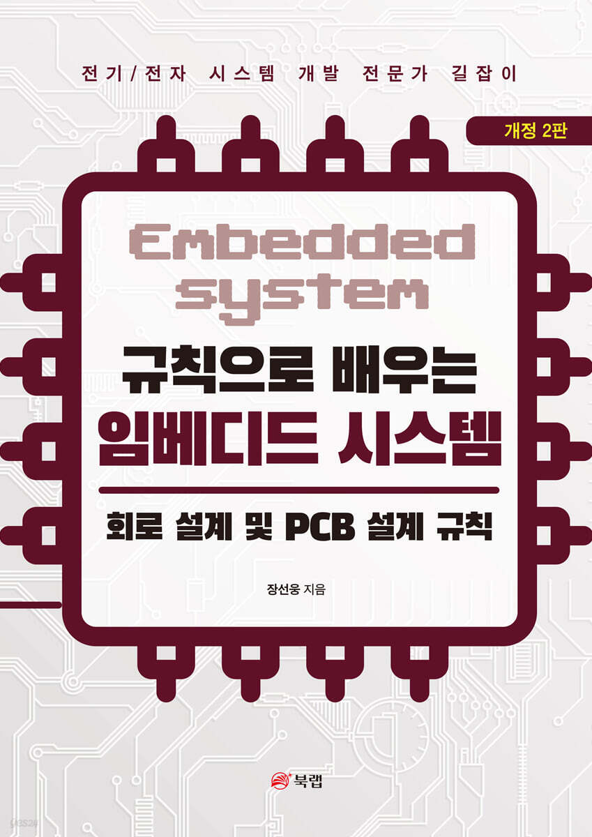
Embedded Systems: Circuit Design and PCB Design Rules
 |
Description
Book Introduction
A Guide for Electrical/Electronic Systems Development Professionals
Electrical/Electronics from a Veteran Engineer
A clear roadmap for embedded system development!
"The best way to read this book is to read it repeatedly as if you were reading a novel to understand the basic theory and
"It's about understanding the relationships between system development rules."
Many people learn the basic theories of electronic systems, but are unable to apply them in practice.
This phenomenon is due to a lack of overall knowledge of how individually learned theories are used in system development.
In this state, even if the development career is long, the work knowledge that has been done is not fully accumulated as one's own ability.
Some say that developing electronic systems is easy these days because open platforms such as Arduino and Raspberry Pi make it quite easy to implement functions.
However, developing a system that not only implements functions but also has high performance, stability, and noise robustness is by no means an easy task.
Developing such a robust system requires a lot of theory and development know-how based on that theory.
For this reason, this book recaps the overall basic theory and discusses how to use it.
It also covers the theory and methods for creating system development rules.
We need to look at the rules of thumb that have already been created based on the experiences of numerous engineers and figure out why and how they came to be.
Only then can you modify and interpret the rules to fit your system and make them your own.
Electrical/Electronics from a Veteran Engineer
A clear roadmap for embedded system development!
"The best way to read this book is to read it repeatedly as if you were reading a novel to understand the basic theory and
"It's about understanding the relationships between system development rules."
Many people learn the basic theories of electronic systems, but are unable to apply them in practice.
This phenomenon is due to a lack of overall knowledge of how individually learned theories are used in system development.
In this state, even if the development career is long, the work knowledge that has been done is not fully accumulated as one's own ability.
Some say that developing electronic systems is easy these days because open platforms such as Arduino and Raspberry Pi make it quite easy to implement functions.
However, developing a system that not only implements functions but also has high performance, stability, and noise robustness is by no means an easy task.
Developing such a robust system requires a lot of theory and development know-how based on that theory.
For this reason, this book recaps the overall basic theory and discusses how to use it.
It also covers the theory and methods for creating system development rules.
We need to look at the rules of thumb that have already been created based on the experiences of numerous engineers and figure out why and how they came to be.
Only then can you modify and interpret the rules to fit your system and make them your own.
- You can preview some of the book's contents.
Preview
index
I.
SYSTEM theory
1.
Electrical/Electronic Fundamentals
1.1.
Voltage and current
1.2.
Resistance, capacitance, inductance
1.3.
Kirchhoff's laws
2.
Types of systems and signals
2.1.
linear system
2.2.
Linearity of electrical characteristics
2.3.
Types of signals
3.
Frequency component decomposition of a signal
3.1.
Time domain and frequency domain
3.2.
Fourier series
3.3.
Fourier transform
4.
Interpreting the system's output
4.1.
Convolution in the time domain
4.2.
Fourier transform in frequency domain analysis
4.3.
Laplace transform
5.
transfer function
5.1.
Laplace transfer function
5.2.
Board leader
5.3.
Impedance of electrical/electronic systems
6.
System response characteristic items
6.1.
Response characteristics items in the time domain
6.2.
Frequency domain characteristic items
6.3.
The relationship between time and frequency domains as seen from a square wave
7.
Standard form of Laplace transfer function
7.1.
Primary standard system
7.2.
Secondary standard system
8.
System stability
8.1.
System stability assessment
II.
Basic Electrical/Electronic Theory
1.
Basic characteristics of electrical/electronic devices
1.1.
Distinction between electrical and electronic components
1.2.
Understanding the basic characteristics of electrical/electronic devices
2.
Basic electrical/electronic components
2.1.
resistance element
2.2.
capacitor
2.3.
Inductor
2.4.
diode
2.5.
transistor
2.6. MOSFET
2.7. OPAMP
2.8. CMOS and TTL
2.9. MCU
III.
Basic theory of noise
1.
Types of noise
1.1.
Types of noise
1.2. Noise current path viewed through RC filter
2.
Classification by noise path
2.1.
Conductive noise
2.2.
Inductive noise
2.3.
Radiated noise (electromagnetic waves)
3.
Classification by noise direction
3.1.
Normal mode noise
3.2.
Common mode noise
4.
Grounding
4.1.
About the ground
4.2.
Purpose and types of grounding
4.3.
Methodological distinction of grounding
5.
Interpreting ringing noise
5.1. Ringing analysis using RLC modeling
5.2.
Ringing Analysis through Transmission Line Theory
5.3.
Transmission line judgment criteria
5.4.
Impedance matching method
6.
Types of loads and noise
6.1.
resistive load
6.2.
Inductance load
6.3.
capacitance load
7.
EMC Certification Standards for Electrical/Electronic Equipment
7.1. Meaning of EMC and Certification Test
7.2. EMS (Electromagnetic Compatibility)
7.3. EMI (Electromagnetic Interference)
8.
Electrical safety certification standards
8.1.
Terminology of standard judgment criteria
8.2.
Spatial distance and creepage distance
8.3.
Electrical safety test items
IV.
Circuit and PCB design process
V.
Circuit design rules
1.
Establishing circuit design rules
1.1.
Circuit functions and performance
1.2.
Circuit stability
1.3.
Circuit safety
1.4.
etc
2.
Commercial power circuits and protection devices
2.1.
Overcurrent protection circuit
2.2.
Overvoltage protection circuit
2.3. AC-DC power conversion
2.4.
circuit protection devices
VI. PCB Design Rules
1. PCB Basics
1.1. PCB basic structure
1.2. PCB manufacturing process
1.3. PCB design sequence
2. PCB layer decision rules
2.1. PCB layer structure
2.2. PCB Layer Usage Rules
3.
Layout rules for parts
3.1.
Partitioning plan for parts placement
3.2.
The order of placement of parts
3.3.
Considerations for Component Placement
4.
Signal wire wiring rules
4.1.
General wiring sequence
4.2.
Determining the thickness and width of the pattern
4.3.
Pattern spacing rules
4.4.
Wiring rules
4.5.
Rules for using Via
4.6.
Power and Ground Wiring Rules
4.7.
Reinforcement of vulnerable areas such as high current/EMC/heat generation
VII.
[Reference] Function and Reliability Test
SYSTEM theory
1.
Electrical/Electronic Fundamentals
1.1.
Voltage and current
1.2.
Resistance, capacitance, inductance
1.3.
Kirchhoff's laws
2.
Types of systems and signals
2.1.
linear system
2.2.
Linearity of electrical characteristics
2.3.
Types of signals
3.
Frequency component decomposition of a signal
3.1.
Time domain and frequency domain
3.2.
Fourier series
3.3.
Fourier transform
4.
Interpreting the system's output
4.1.
Convolution in the time domain
4.2.
Fourier transform in frequency domain analysis
4.3.
Laplace transform
5.
transfer function
5.1.
Laplace transfer function
5.2.
Board leader
5.3.
Impedance of electrical/electronic systems
6.
System response characteristic items
6.1.
Response characteristics items in the time domain
6.2.
Frequency domain characteristic items
6.3.
The relationship between time and frequency domains as seen from a square wave
7.
Standard form of Laplace transfer function
7.1.
Primary standard system
7.2.
Secondary standard system
8.
System stability
8.1.
System stability assessment
II.
Basic Electrical/Electronic Theory
1.
Basic characteristics of electrical/electronic devices
1.1.
Distinction between electrical and electronic components
1.2.
Understanding the basic characteristics of electrical/electronic devices
2.
Basic electrical/electronic components
2.1.
resistance element
2.2.
capacitor
2.3.
Inductor
2.4.
diode
2.5.
transistor
2.6. MOSFET
2.7. OPAMP
2.8. CMOS and TTL
2.9. MCU
III.
Basic theory of noise
1.
Types of noise
1.1.
Types of noise
1.2. Noise current path viewed through RC filter
2.
Classification by noise path
2.1.
Conductive noise
2.2.
Inductive noise
2.3.
Radiated noise (electromagnetic waves)
3.
Classification by noise direction
3.1.
Normal mode noise
3.2.
Common mode noise
4.
Grounding
4.1.
About the ground
4.2.
Purpose and types of grounding
4.3.
Methodological distinction of grounding
5.
Interpreting ringing noise
5.1. Ringing analysis using RLC modeling
5.2.
Ringing Analysis through Transmission Line Theory
5.3.
Transmission line judgment criteria
5.4.
Impedance matching method
6.
Types of loads and noise
6.1.
resistive load
6.2.
Inductance load
6.3.
capacitance load
7.
EMC Certification Standards for Electrical/Electronic Equipment
7.1. Meaning of EMC and Certification Test
7.2. EMS (Electromagnetic Compatibility)
7.3. EMI (Electromagnetic Interference)
8.
Electrical safety certification standards
8.1.
Terminology of standard judgment criteria
8.2.
Spatial distance and creepage distance
8.3.
Electrical safety test items
IV.
Circuit and PCB design process
V.
Circuit design rules
1.
Establishing circuit design rules
1.1.
Circuit functions and performance
1.2.
Circuit stability
1.3.
Circuit safety
1.4.
etc
2.
Commercial power circuits and protection devices
2.1.
Overcurrent protection circuit
2.2.
Overvoltage protection circuit
2.3. AC-DC power conversion
2.4.
circuit protection devices
VI. PCB Design Rules
1. PCB Basics
1.1. PCB basic structure
1.2. PCB manufacturing process
1.3. PCB design sequence
2. PCB layer decision rules
2.1. PCB layer structure
2.2. PCB Layer Usage Rules
3.
Layout rules for parts
3.1.
Partitioning plan for parts placement
3.2.
The order of placement of parts
3.3.
Considerations for Component Placement
4.
Signal wire wiring rules
4.1.
General wiring sequence
4.2.
Determining the thickness and width of the pattern
4.3.
Pattern spacing rules
4.4.
Wiring rules
4.5.
Rules for using Via
4.6.
Power and Ground Wiring Rules
4.7.
Reinforcement of vulnerable areas such as high current/EMC/heat generation
VII.
[Reference] Function and Reliability Test
Into the book
2.3.
Types of signals
A signal is a transmission medium that conveys meaningful and useful information from the sender to the receiver.
Anything that can convey information, such as gestures, sounds, or light, can be a medium of communication.
For example, in electrical/electronic systems, transmission media include voltage, current, and electromagnetic fields.
2.3.1.
Types of signals
The system ultimately achieves its desired goal by processing signals. Here, we will learn about the types and characteristics of representative signals used to interpret the characteristics of the system.
These signals are important signals that allow us to interpret the characteristics of the system by giving them as input signals to the system and checking the output response.
We will look at the use of each signal later.
go.
Periodic vs. Aperiodic Signals
Signals can be divided into periodic signals, whose waveform repeats at regular time intervals, and aperiodic signals, which do not repeat.
The mathematical expression for a periodic signal that has the same value at regular time intervals, i.e. at regular cycles, is as follows.
--- p.42 From 『I』
2.7.4.
Non-inverting amplifier circuit design
Let's design a non-inverting amplifier circuit with 11 times voltage amplification using OPAMP for a 10KHz signal.
A. OPAMP selection
When selecting an OPAMP, the driving voltage is selected by checking the signal input voltage and the OPAMP output voltage so that it can operate within the OPAMP voltage range.
The frequency response bandwidth should be at least twice that of the signal, and usually 5 to 10 times or more is preferred to take into account phase delay, etc.
If you want a 5x margin, since GBP (Gain Bandwidth Product) = ACL × Bandwith, you can select an OPAMP with a GPB of 11x Closed Loop gain × 10KHz × 5 = 550KHz or more.
In addition, the characteristics of the OPAMP seen above, such as input offset voltage, input bias current,
Select an appropriate OPAMP by checking the slew rate, differential and common-mode maximum voltages, etc.
--- p.307 from 『II』
2.4.
circuit protection devices
We previously looked at protection methods against ESD and surge noise in power circuits.
Here we will learn how to protect the DC digital port.
Signal terminals or IO terminals connected to the outside of the system must be protected against overvoltage/overcurrent, and the following protection methods are available.
Methods for protecting IO ports include non-isolation circuits that are not isolated from the system's power supply and are a countermeasure against normal mode noise, and isolation circuits that are completely isolated from the system's power supply and can respond to both normal mode and common mode.
If a port that needs to be connected to an external system needs to be protected by a non-isolated circuit while also responding to common mode noise, a circuit with a capacitor connected to ground, such as a common mode coil and a Y capacitor, can be used.
Types of signals
A signal is a transmission medium that conveys meaningful and useful information from the sender to the receiver.
Anything that can convey information, such as gestures, sounds, or light, can be a medium of communication.
For example, in electrical/electronic systems, transmission media include voltage, current, and electromagnetic fields.
2.3.1.
Types of signals
The system ultimately achieves its desired goal by processing signals. Here, we will learn about the types and characteristics of representative signals used to interpret the characteristics of the system.
These signals are important signals that allow us to interpret the characteristics of the system by giving them as input signals to the system and checking the output response.
We will look at the use of each signal later.
go.
Periodic vs. Aperiodic Signals
Signals can be divided into periodic signals, whose waveform repeats at regular time intervals, and aperiodic signals, which do not repeat.
The mathematical expression for a periodic signal that has the same value at regular time intervals, i.e. at regular cycles, is as follows.
--- p.42 From 『I』
2.7.4.
Non-inverting amplifier circuit design
Let's design a non-inverting amplifier circuit with 11 times voltage amplification using OPAMP for a 10KHz signal.
A. OPAMP selection
When selecting an OPAMP, the driving voltage is selected by checking the signal input voltage and the OPAMP output voltage so that it can operate within the OPAMP voltage range.
The frequency response bandwidth should be at least twice that of the signal, and usually 5 to 10 times or more is preferred to take into account phase delay, etc.
If you want a 5x margin, since GBP (Gain Bandwidth Product) = ACL × Bandwith, you can select an OPAMP with a GPB of 11x Closed Loop gain × 10KHz × 5 = 550KHz or more.
In addition, the characteristics of the OPAMP seen above, such as input offset voltage, input bias current,
Select an appropriate OPAMP by checking the slew rate, differential and common-mode maximum voltages, etc.
--- p.307 from 『II』
2.4.
circuit protection devices
We previously looked at protection methods against ESD and surge noise in power circuits.
Here we will learn how to protect the DC digital port.
Signal terminals or IO terminals connected to the outside of the system must be protected against overvoltage/overcurrent, and the following protection methods are available.
Methods for protecting IO ports include non-isolation circuits that are not isolated from the system's power supply and are a countermeasure against normal mode noise, and isolation circuits that are completely isolated from the system's power supply and can respond to both normal mode and common mode.
If a port that needs to be connected to an external system needs to be protected by a non-isolated circuit while also responding to common mode noise, a circuit with a capacitor connected to ground, such as a common mode coil and a Y capacitor, can be used.
--- p.543 From 『V』
GOODS SPECIFICS
- Date of issue: October 23, 2024
- Page count, weight, size: 642 pages | 1,200g | 182*257*31mm
- ISBN13: 9791172243555
- ISBN10: 1172243557
You may also like
카테고리
korean


korean

![GQ KOREA Mark (Monthly): December [2025]](http://librairie.coreenne.fr/cdn/shop/files/8ef265dbbfbf186523ed75ba7319009d.jpg?v=1765340328&width=3840)


